
Hi guys,
As I wrote in the last post, here we are with the implementation of the motor controller that uses the encoder feedback.
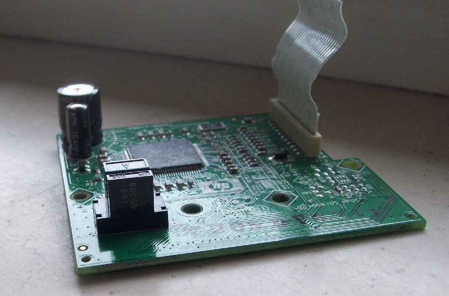
I suggest you to read the previous post so to catch up with the point.Here there is the link https://cuverita.wordpress.com/2013/06/30/how-to-master-an-hp-printer-optical-encoder-carriage/
We will see how to set the proper speed and direction of the motor that moves the carriage considering the position coming from the optical incremental encoder.In fact it could be an easy way to make some practise with a PID controller.
In order to do that, we need a MCU.This time I chose a PIC18F2523 that is programmed using the PicKit2 while the coding is done with MpLab X IDE and XC8 compiler.
The parts to develop are:
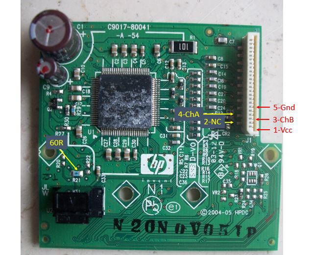
1)How to understand out position using the channels of the encoder
2)How to set a particular speed and direction to the motor that moves the carriage
3)How to use a PID algorithm to control the system.
Ok….let’s proceed with order and, as always , the divide et impera method will help us to make the things straight forward.
I suggest you some web page to read so that the things will be more clear before starting:
1)
http://mechatronics.mech.northwestern.edu/design_ref/sensors/encoders.html
http://www.pengurobotics.com/projects/avr_hp_encoder
2)
http://www.mikroe.com/chapters/view/6/
http://www.pyroelectro.com/tutorials/h_bridge_4_transistor/
http://workshops.ist.utl.pt/arduino-lessons/lesson-ii-3-inductive-load-control/
3)
http://courses.csail.mit.edu/6.141/spring2011/pub/lectures/Lec03-MotorControl.pdf
http://ww1.microchip.com/downloads/en/AppNotes/00964A.pdf
As you can see from the resources I chose for you,I want to take and easy and applicative approach.
I remember the long course I had at the university about robust controller.The professor started with theoric stuff like: phase margin,bandwith in open loop,overshoot,rise time,settlement period etc…
For you I will skip all this shit and we will go straight with the last part of the course.In fact after almost 3 moths of explaination we came up with the standard industrial controllers better known as ProportionalIntegralDerivative controller.
The most of the closed loop controls are possible because of it and sometimes PIDs are used even if are not the proper way to rule the system.Ok,we are engineers and the time is money,so…why don’t if it works!
Well,we are going to control this motor that works at a nominal voltage of 18Volts.Considering that I have a power supplier of 14V,we will provide only this voltage to it,through an H-bridge.

Moreover I glued a limit switch that is used to reset the count of the steps of the encoder,during the initialization.

Here we have the schematic of the project

As always an image explains better than thousand words.Anyway a short commend doesn’t cost that much:
Here you have the complete source code in XC8. Some parts are inspired by the reference I gave you above.For instance the finite state machine that provides the position from the encoder output is from the third link.I swear that the rest of the code is brand new:
http://rapidshare.com/files/2444778370/encoder_pid.zip
(the password of the zip file is:”cuverita”)
For the sake of keeping the reference position, I implemented a PI controller(no derivative) in this strange way:
int pi_controller (int ref,int now){
static int integ=0;
int err=0;
int out=0;
err=ref-pos;
out=shift_number(err,KP_SHIFT);
integ=integ+shift_number(err,KI_SHIFT);
//anti wind-up code
if(err<0)
err=-1*err;
if(err<EPS){
out=out+integ;//use it if near settlement
}else
integ=0;//clear the accumulated
return out;
}
In fact I wanted to have a Kp and Ki much smaller than one.The most efficient way to divide a number is to shift it right with a bitwise operation(>>) .It saves computational time so to control the system quickly when needed.
Eventually a clip of the carriage moving.You can see an initialization that uses tha limit switch,then a change of reference position given by the pression on the switch.
The reference position is taken activelly with a proportional action,the more I push and the more the displacemente increases.This cause an error=reference-position that is compensated by an higher voltage to the motor(PWM duty cycle).
I’m available for any question…
Stay tuned!

