Sorry but this time I’m going to write the post in my mother tongue. This is because I want to explain how to make a very easy PCB’s to young students that may not understand English.
Ci sono molte recensioni del servizio di PCB sharing chiamato OSH Park ma nessuna (ancora) è in Italiano. La scheda che ho realizzato con KiCad è davvero semplice e a scopo dimostrativo. Utilizza componenti PDIP molto comuni come l’operazionale LM324, resistori e condensatori though hole. Ovviamente i più smaliziati possono divertirsi con la tecnologia SMD(SMT) anche se molto più difficile da saldare sulla piastra.
Mi rivolgo soprattutto a studenti di istituti tecnici o professionali a cui piace sporcarsi le mani. Il nostro paese tende a scordarsi di voi e di quanto la vostra formazione sia importante per l’innovazione. Vi do un consiglio: se siete predisposti a sporcarvi le mani (come me), non sentitevi a disagio con questa vostra necessità! Siate curiori, fate pratica, errori e correzioni. Anche il mercato del lavoro ve ne darà conto perchè dimostrare di poter fare qualcosa di pratico e funzionante vi porterà tra i primi della lista.
It took a long time but eventually I have everything I ordered from the web.
The items I ordered are:
1)Balloon (Blimp, Silver)- 52″x37″ – 1X
2)Motor-7mm 3.3 Ohm – 2X
3)Propeller – 65mm – 2X
(from Plantraco Canada)
4)Pololu USB AVR Programmer – 1X
5)Baby Orangutan B-328 – 1X
6)Battery LiPo 2S/1P 7,4V 350 mAh 25C – 1X
7)Battery LiPo 2S/1P 7,4V 550 mAh 20C – 1X
8)Battery charge LiPo PolyCharge 12V – 1X
9)Ultrasonice range finder XL MaxSonar EZ2 – MB1220 – 1X
10)Micro Servo Hitec HS 55 – 1X
(from RobotStore.it)
11)Pan / tilt SPT50 mechanics – 1X
(from RobotShop.eu)
I wrote the number of items needed for the project but actually there are some backup parts.
There is the Helium misssing from the list because I’m working to find it to some local dealer.
Most likely I will have to buy some other small electrical components and find some wire.Anycase these are the main stuff I will need.
I received my stuff here in Tampere(FI) without problems from the european stores.I had to cope with some burocracy about the envelope coming from Canada.
In fact Tulli(finnish import agency) wanted me to provide: Evidence of my study activity, list of components in the package, declaration from the university department about my need of those parts and of course they checked my ID.
Maybe next time I will ask to a finnish friend to go in case of me.I may understand that a long black beard italian, with a deep voice and a Fonzie’s black leather jacket may look suspicious 🙂
After twice I have been at that office(lost in the industrial side of Tampere) I have been able to receive my package at home.
How’s the summer going?Here in Italy is terribly HOT (today +35) and, as usual for me, I don’t care to sweat liters close to the welding station 🙂
Today I discovered a tmp102 temperature sensor in the drawer.I both it a long time ago on Sparkfun with its breakout pcb for something like 5€.So why don’t build a digital thermometer with a 7-segment like interface?
The main requirement for this project is: Don’t buy anything!At this point I’m poor and I can’t spend more money 😦
Ok…great!Let’s see what we need:
Sensor? OK
Protoboard? OK
Battery pack? OK
Voltage regulators? OK
MCU? i can use a pic18f2523 so… OK
Leds? uhc….if I want to make it with two leds per segment I must change color but….OK
Resistances? uhc again…I don’t have any more small values like 220 or 330 ohms.Well I can limit the current in some other way 🙂
In the end I came up with this schematic:
I’m using a digital potentiometer through spi in order to change the base current of the pnp.In this way depending on the number of segments turned on I can limit the current flowing through the leds.Remember that the leds, apart the colors, are all the same(same Vfwd and Iled)
The rest of the schematic has just some digital stuff.
The software handles the i2c and spi communication and enables the npn transistors depending on the number to represent.
There is a PWM like switching for the leds in order to reduce the power consumption without changing too much the brightness.
The worst case current consumption is about 12mA.This is pretty much considering the 4500-5000mAh of the battery package.
For this reason the leds are turned on for 4 seconds every 40 seconds or when there is a change in the temperature.A change of temperature is filtered by an hysteresis mechanism and the measurement is the average value of 20 measurements per second.
This time I don’t feel like publishing the source code.
Of course it could be better to have it in a container but I didn’t have anything to mod or money to spend for a new one.
Now the funny part…the test:
After some time it came back to the actual temperature: +32 degs!
We will see how to set the proper speed and direction of the motor that moves the carriage considering the position coming from the optical incremental encoder.In fact it could be an easy way to make some practise with a PID controller.
In order to do that, we need a MCU.This time I chose a PIC18F2523 that is programmed using the PicKit2 while the coding is done with MpLab X IDE and XC8 compiler.
The parts to develop are:
1)How to understand out position using the channels of the encoder
2)How to set a particular speed and direction to the motor that moves the carriage
3)How to use a PID algorithm to control the system.
Ok….let’s proceed with order and, as always , the divide et impera method will help us to make the things straight forward.
I suggest you some web page to read so that the things will be more clear before starting:
As you can see from the resources I chose for you,I want to take and easy and applicative approach.
I remember the long course I had at the university about robust controller.The professor started with theoric stuff like: phase margin,bandwith in open loop,overshoot,rise time,settlement period etc…
For you I will skip all this shit and we will go straight with the last part of the course.In fact after almost 3 moths of explaination we came up with the standard industrial controllers better known as ProportionalIntegralDerivative controller.
The most of the closed loop controls are possible because of it and sometimes PIDs are used even if are not the proper way to rule the system.Ok,we are engineers and the time is money,so…why don’t if it works!
Well,we are going to control this motor that works at a nominal voltage of 18Volts.Considering that I have a power supplier of 14V,we will provide only this voltage to it,through an H-bridge.
Moreover I glued a limit switch that is used to reset the count of the steps of the encoder,during the initialization.
Here we have the schematic of the project
As always an image explains better than thousand words.Anyway a short commend doesn’t cost that much:
Here you have the complete source code in XC8. Some parts are inspired by the reference I gave you above.For instance the finite state machine that provides the position from the encoder output is from the third link.I swear that the rest of the code is brand new:
For the sake of keeping the reference position, I implemented a PI controller(no derivative) in this strange way:
int pi_controller (int ref,int now){
static int integ=0;
int err=0;
int out=0;
err=ref-pos;
out=shift_number(err,KP_SHIFT);
integ=integ+shift_number(err,KI_SHIFT);
//anti wind-up code
if(err<0)
err=-1*err;
if(err<EPS){
out=out+integ;//use it if near settlement
}else
integ=0;//clear the accumulated
return out;
}
In fact I wanted to have a Kp and Ki much smaller than one.The most efficient way to divide a number is to shift it right with a bitwise operation(>>) .It saves computational time so to control the system quickly when needed.
Eventually a clip of the carriage moving.You can see an initialization that uses tha limit switch,then a change of reference position given by the pression on the switch.
The reference position is taken activelly with a proportional action,the more I push and the more the displacemente increases.This cause an error=reference-position that is compensated by an higher voltage to the motor(PWM duty cycle).
I’m back in Italy for the summer and considering I don’t know how to spend my time I decided to start some hack.
It was 34 celsius and I decided to soffer the terrible hot temperature of my my room/lab starting opening a pretty old printer that a friend gave me.This is a HP PSC 1510 AllInOne that ended his life just because of a new HP knocked at the door.
After I removed the screws I saw a nice carriage with DC motor and optical encoder.That’s cool because you can do many interesting things with one of these carriage.
I’m sure I’m not the first in the world to do that but I think it could be interesting to sum up what was the research on internet and the coding I needed to do.It could be an easier start for some other guy who finds the same situation.
First step:Who knows something about this printer?Let’s try to google that…
1)It seems that guy managed good the task.In this case he uses a comparator because the output of the encoder is a sinusoidal shape signal that must be compared with the half of its amplitute to become a squared shape signal. In that case he needed to arrange the threshold so to have an logic high if over half of the power supply voltage.
2)Great!There are some picture of the pinout of several optical encoder produced by Agilent. There is even the Agilent 9981 that I need
The AEDS-962x have the same pinout and the same electronics of the Agilent 9981
There is a built-in comparator with pull-up(2.5K) so that in this case the ouptut signal has a squared shape ready to be used with a common I/O port without the use of MCU’s comparators.
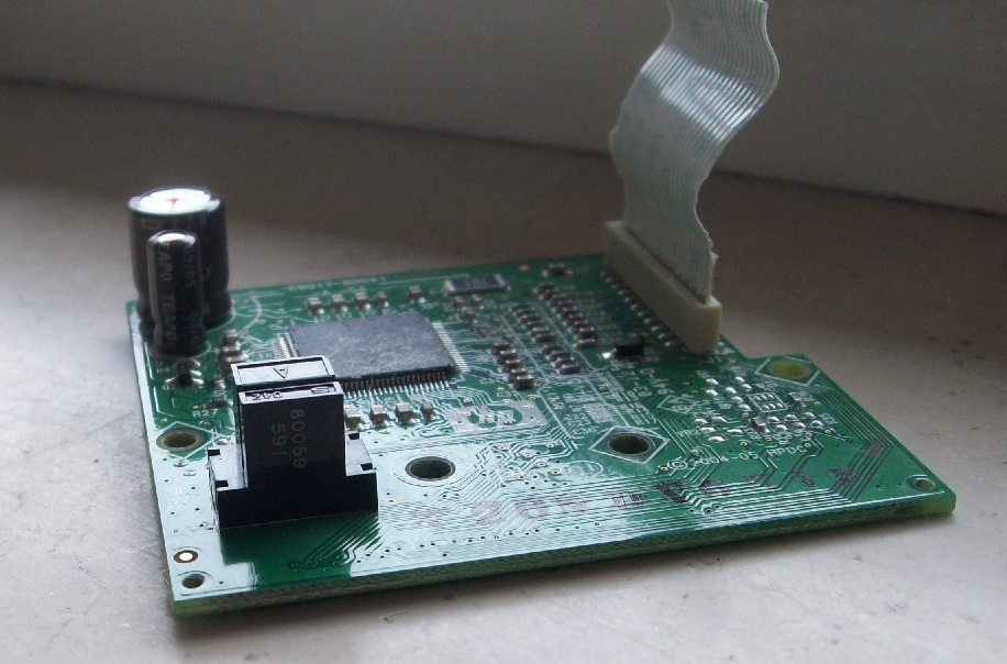
Perfect…let’s see how to use the stuff we have.For sure we want to keep the perfect mechanics that works around the encoder so we must access the sensor without welding it out from the board.
An easy way to do that is welding some wire from the strip connector that acts as interface.Using the multimeter in ‘diode’ mode we can figure out to which pin the power supply and the two channels go.
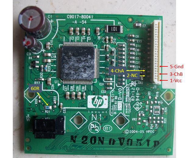
As you can see from the picture there is some uggly welding coming out from the sides of the connector.The pin out in in the picture too.
There is a 60 Ohm resistance between the anode of the led and Gnd.In this way the current flowing in it is limited to about 30mA
Quod erat demonstrandum once powered up the sensor(3V) the output of the channels are 0V or almost 3V for both channels.
I implemented already some code for the PIC18F2523 mcu with XC8 in order to determine the position of the carriage from the encoder.This will be the topic for the next post.
I hope that my explaination, apart the latin, was clear and that this post could help you to take some Hp printer out form the garbage 😉
That’s it for today!I’m working on the c code for the MCU so to implement a robust control of the movement.
It was the spring of 2010.I was in Verres a small village in the Valle d’Aosta region. I had the terrible idea to study Mechatronics engineering and the best place in Italy was that.
It was a period in which I was studying in Politecnico di Torino and I met a random guy called Andrea.We were looking for a flat and we decided to be flat mate.Unfortunatelly for us it was not the right place to make party because the owner suffered a terrible insomnia and so we needed to be fu___in’ silent and quiet (not only during the evening).
Fortunately he had a robot called Sirio, good mechanic but a bit slow.It could react changing path when colliding against objects.In other terms it was a bit like a SumoRobot but really light.
We had a lot of time (sad place for students) and working on it was quite silent apart some hammer blow (and some Andrea’s swearing).
First of all we decided to take apart the old electronics made with an 8 bit MCU and I proposed to use a module that i bough for a handful of €.It was a motor controller form Phidgets (http://www.phidgets.com/products.php?category=19&product_id=1060_0) that now seems to be discontinued.
They gave with the module some API that could be easily used with VisualBasic.net and following the docs I made a simple application to interface them.
As first step, we tried to send some command to the two separated motors.Everything was ok then,next step, why don’t controll it with the keyboard?Ok,just use some DirectX control already in the design tool.Everything works!We could control it intuitively.
Why don’t implement a bluetooth remote control?It is just a matter of emulate a keyboard and the stuff is done.
I was making some experiment during my spare time on something called AForge.net framework(http://www.aforgenet.com/framework/).This is a framework that every programmer can use to fetch images from a webcam and process them with some algorithms already implemented.
I used with a brandless camera that was so chip that I was suprised to see that i was really working.Anyway it was possible to understand the position of some shape in the picture.You just needed a well defined colored object,a filter to isolate that and a function to return the position of the equivalent rectangular after the filtering.
Now there is the interesting part:
We have a robot,we have a control from a pc,we have the image algorithms.
I said :Hei Bulga!Why don’t we merge the pieces?!
It was just enough to make it go on straight if the colored object was in the top of the image and so on for every direction.
We came up with a small robot that could work in three modes:
Automatic,follow commands from a red laser pointer
Manual,controlled form keyboard
Manual,controlled from a bluetooth(keyboard emulation)
No!Thanks but I am an average guy who does everything but that.
Yes!This is the answer!Everyone who is the average technician/geek/nerd though at least to drive one of whose strange machines.
Unfortunatelly for you I didn’t make anything even close to a real and heavy machine but I started doing something better.
I just attach a clip that shows my prototipe and I will go through the details of the electronics and the structure in some future post.
How does it work in general?
The prototipe has a sensor that determines the distance from the ground and then a microcontroller commands a current loop that pilots the motor and the propeller.Modifying this flux of air you adjust the height so to keep it as constant as possible even if there are some disturbance.
It has a the loop has a second order dynamic,so in €:it reaches the reference value going above and under it but minimizing the error every time.
After a reasonable time needed to start the motor to a default value the controller starts to work.After a bit I removed some weight and you can see that it can handle a constant disturbance.
Figure 1 from “High accuracy settling time measurements” (Photo credit: Wikipedia)
In the clip I just complain and swear in some latin language about the power MOSFET because it has a massive overheating.This leads to a terrible stink of metal.At half of that I try to explain something with my deep voice but it was too boring an theoric so maybe I will focus on that later on.


