
Hei guys!
I’m back in Italy for the summer and considering I don’t know how to spend my time I decided to start some hack.
It was 34 celsius and I decided to soffer the terrible hot temperature of my my room/lab starting opening a pretty old printer that a friend gave me.This is a HP PSC 1510 AllInOne that ended his life just because of a new HP knocked at the door.
After I removed the screws I saw a nice carriage with DC motor and optical encoder.That’s cool because you can do many interesting things with one of these carriage.
I’m sure I’m not the first in the world to do that but I think it could be interesting to sum up what was the research on internet and the coding I needed to do.It could be an easier start for some other guy who finds the same situation.
First step:Who knows something about this printer?Let’s try to google that…
The best resources for it are:
1)http://www.pengurobotics.com/projects/avr_hp_encoder
2)http://reprap.org/wiki/Optical_encoders_01
I’d like to comment these two resources:
1)It seems that guy managed good the task.In this case he uses a comparator because the output of the encoder is a sinusoidal shape signal that must be compared with the half of its amplitute to become a squared shape signal. In that case he needed to arrange the threshold so to have an logic high if over half of the power supply voltage.
2)Great!There are some picture of the pinout of several optical encoder produced by Agilent. There is even the Agilent 9981 that I need
In fact one of the pictures from the second link http://reprap.org/wiki/File:FD_opto_sensor_pinout_02.JPG has the pinout of the Agilent sensor mounted on the printer carriage.Moreover after some further research I have found this http://pdf.datasheetcatalog.com/datasheet2/a/0a46za47kk0rg2x0izood71i9apy.pdf
The AEDS-962x have the same pinout and the same electronics of the Agilent 9981
There is a built-in comparator with pull-up(2.5K) so that in this case the ouptut signal has a squared shape ready to be used with a common I/O port without the use of MCU’s comparators.
Perfect…let’s see how to use the stuff we have.For sure we want to keep the perfect mechanics that works around the encoder so we must access the sensor without welding it out from the board.
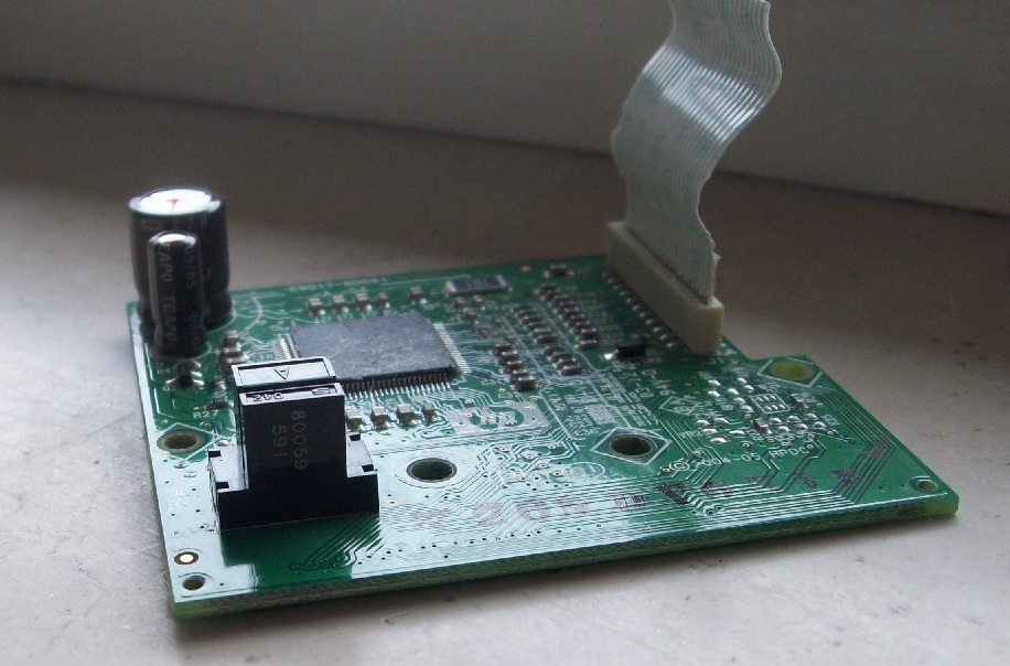
An easy way to do that is welding some wire from the strip connector that acts as interface.Using the multimeter in ‘diode’ mode we can figure out to which pin the power supply and the two channels go.
As you can see from the picture there is some uggly welding coming out from the sides of the connector.The pin out in in the picture too.
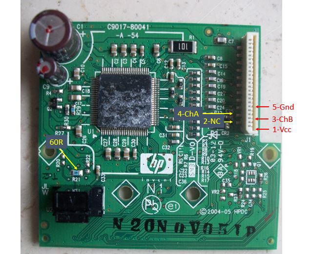

There is a 60 Ohm resistance between the anode of the led and Gnd.In this way the current flowing in it is limited to about 30mA
Quod erat demonstrandum once powered up the sensor(3V) the output of the channels are 0V or almost 3V for both channels.
I implemented already some code for the PIC18F2523 mcu with XC8 in order to determine the position of the carriage from the encoder.This will be the topic for the next post.
I hope that my explaination, apart the latin, was clear and that this post could help you to take some Hp printer out form the garbage 😉
That’s it for today!I’m working on the c code for the MCU so to implement a robust control of the movement.
Stay tuned!

[…] Cuverita Look with the eyes of curiosity « How to master an Hp printer optical encoder carriage […]
Hi.
Could you show me picture wit the pinout of Agilent 9981?
In this place: http://reprap.org/wiki/File:FD_opto_sensor_pinout_02.JPG
pins are marked in another way than in Agilent AEDS-962x datasheet: Agilent AEDS-962x .
Could you tell me, which one is correct?
I also want to make and optical, linear encoder using this sensor and some uC.
Greetings
How do you get the channel A and channel B signal of the encoder? I have an Agilent 09845 encoder from an Hp printer and thanks to your post I figure out that are sine signals.
Have you ever thought about including a little bit more than just your articles?
I mean, what you say is important and everything.
Nevertheless think about if you added some great images or video clips to give
your posts more, “pop”! Your content is excellent but with pics and video clips,
this blog could certainly be one of the greatest in its
field. Terrific blog!